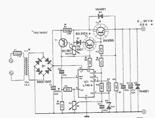
A very lab adjustable power supply that can provide an output voltage between 0 and 60 volts can be designed using this circuit diagram . This lab power supply can be designed with LM723 chip or for higher output voltages, with L146 .Output current is also adjustable, but once established, is always effective. Table 1 shows the values to be modified to have three different versions of the maximum output voltage (30, 40 and 60 V).
Electrical diagram below shows the alternative 40 V / 0.8 using L146 chip because it can stabilize higher output voltage, much better than the LM723. Normally, 2 V is the minimum voltage stabilized that even an integrated circuit can provide. Resistive network R3, R4 and R5, R6 "kill" this restriction so that output can be set to 0 V with potentiometer P2.

Depending on the output requirements, will be decided on the type and the semiconductor capacitors to be used. Output current must be limited so as to keep power dissipation of 40 W. T3 under maximum output current for 40 V version is 0.8 A. It can connect two parallel 2N3055 transistors (with emitter resistors) to double the current output, but in this case requires a 2 A transformer


0 comments:
Post a Comment